


 English (pdf)
 Article in xml format
 Article references
 Send this article by e-mail
 Cited by SciELO
  Similars in
SciELO
Similars in
SciELO 
 Permalink
Introduction
Plasma and beam devices are employed in ampli ers, oscillators, charged particle accelerators, and high power sources of electromagnetic radiation. They are also used to transport electromagnetic energy and charged particles, and for basic plasma physics research 1.
When the electron beam passes near the grating surface (periodic structure), spontaneous radiations may be excited. This periodic structure can be a metallic corrugated surface with spatial periodicity d and corrugation height h. This radiation was rst observed by Smith and Purcell 2 in 1953. The Smith Purcell radiation (SPR) is a tunable electromagnetic source, which is described by where is the wavelength of the radiated wave from the grating, n is the order of this radiation, is the relative velocity of the charge, and ø is the direction of the radiated wave with respect to this charge.
In the far-infrared or terahertz (THz) region, several theories have been proposed to describe the operation of SPR, and also its application, in a free electron laser (FEL). Schachter and Ron proposed a theory based on the interaction of an electron beam with a wave traveling along the grating. They used some approximation to evaluate the re ection matrix of the grating and found a cubic equation for growth rate, which is consistent with Cherenkov FEL 3. Urata et al. considered this phenomenon experimentally, and observed high power coherent superradiant SP emission in the far infrared (30-100 µm) region 4. SP radiation in the violet and near infrared regions was also detected by Y. Neo et al. 5. Kim and Song, using the interaction of the electrons with a traveling wave, solved the initial problem of the sheet-beam and found a quadratic equation for the exponential growth rate 6. Later Andrews and Brau explained Urata's experiment as bunching of the beam electrons due to the interaction of an evanescent wave with this suficiently high-current beam. They also derived the gain of this radiation, which had cube root dependence on the beam current 7. Also in 2004, Freund et al. 8 developed a linear theory of a grating coupled Smith{Purcell traveling wave in a parallel plate wave guide. They found the linearized dispersion relation for the vacuum structures and the wave{particle interaction in an arbitrary mag- netic eld. Then, D. Li et al. performed simulation and confirmed the theory of Andrews and cowork- ers about the mechanism of superradiation, which happens at integer multiples of the bunching frequency 9. In addition, the growth rate of SPFEL was considered by D. N. Klochkov et al. and found to be proportional to the square root of the sheet electron beam current 10.
Loading dielectric is an important physical mechanism which has been successfully applied to some high power microwave and terahertz systems. A dielectric-loaded grating for 3D Smith Purcell rectangular device is proposed by Cao et al. 11, 12.
They used 3D particle-in-cell simulation to nd the dispersion relations at the operating point, and the growth rates. W. Liu et al. considered a rectangular grating lled with dielectric. They obtained the minimum current for starting the SP oscillator and deduced that the dielectric will decrease this current. Also, they explained the efect of changing the beam parameters on the growth rate 13.
There is no edge efect issue in cylindrical grating driven by an annular beam. Therefore, as the cylindrical gratings are more ecient, with fewer losses than rectangular ones, they are more applicable in radiation sources and considered in many types of research. H. P. Bluem et al. worked on a cylindrical grating exposed by an annular beam. They observed both superradiance and SP radiation 14. S. Hasegawa et al. considered a cylindrical corrugation in a waveguide. They reported BWO operation, excited by a cylindrical surface wave in k-band signal region. Also, they increased the voltage of the beam and observed SP radiation in the u-band and E-band of frequency, which was the result of interaction between the higher modes of the waveguide 15.
Here we present a linear theory of an annular electron beam, magnetized, propagating along a
cylindrical metallic grating. The slots of this grating are lled with dielectric. The results of this paper highlight the basic problem of developing SP-FEL based on cylindrical grating loaded with dielectric. For simplicity, we assume that the system is uniform in the direction parallel to the slots of the grating. The fundamental dynamical equations are presented in section II. The results and discussion are given in section III. The conclusions are considered at the end.
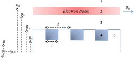
Figure 1: The cross section view of the grating, lled with dielectric. In addition, the annular electron beam.
is drifting along the axial direction with an externally magnetic eld B0.
Theory
Consider a cylindrical grating which is made of an ideal metal. The inner and outer radii of the grating are R1 and R2, respectively as illustrated in Fig. 1. As shown in this gure, d denotes the period of the grating, l is the length of the slot openings (which will be lled with dielectric) and h is the depth of the slots (R2-R1). An annular en beam with inner radius a1 and outer radius a2 = a1 + in a uniform static axial magnetic eld B0 is drifting with velocity v0 along the axis of the grating and very close to it. We assume that there is no transverse disturbed movement in the electron beam. In addition, for simplicity, we assume that the system is uniform in the ' direction.
i. Dispersion relation
The dispersion relation of the modes of this system is the result of considering Maxwell's equations
with the continuity equation and the relativistic momentum equation for electron beams:
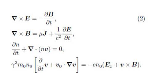
As a consequence, we expand all quantities in terms of an unperturbed part plus a small perturbation as follows: n = n0+ n, v = v0+ Φz, J = J0+ J, E = E and B = B0Φz + B, where n and v are the electron density and velocity, respectively. Unperturbed beam density, n0, is uniform and timeindependent, E and B are the electric and magnetic elds, J = env is the density of current, = (1 v2=c2)1=2 is the relativistic factorc is the velocity of light in free spac.The perturbed density of current is
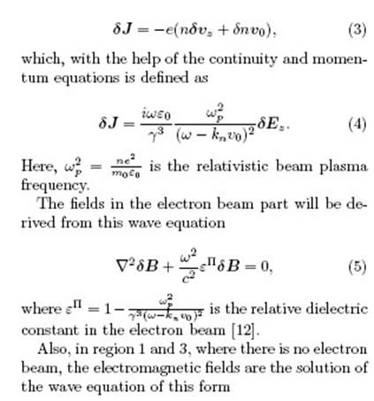
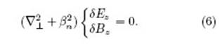
We suppose that the TM mode propagates in this device. And, by applying Floquet's theorem, the radiation elds take the general form
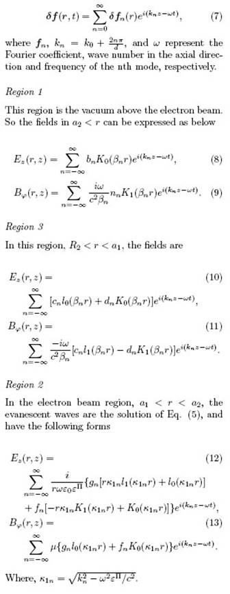
The slot openings (region 4) are lled with dielectric €ͬ. The solutions of the wave equation in this region are
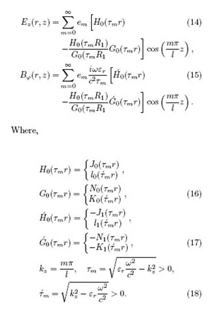
As we assumed k0d <2ת , it is enough to keep just one mode (m = 0) in the slots, so the standing waves will be the elds in this part of the system. Also, there is no eld in the ideal metal of region 5. After applying the continuity conditions for the elds in the border of regions 1-2, 2-3 and 3-4, the dispersion relation will be as below
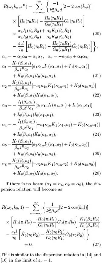
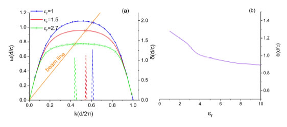
Figure 2: (a) Comparison of dispersion relations for dierent "rs (solid curves). The beam line with voltage 20 kev is also plotted for reference. The growth rate (δ) for each curve, near the intersection (the circles), is indicated by a dash line. (b) The efect of relative dielectric "r on the growth rate.
ii. Growth rate
So far, the dispersion relation of the modes in this configuration has been derived. One of these modes can grow if it is in resonance with the electron beam. So, we assume that the frequency of this mode is ! = !r . Then the Taylor expansion of the dispersion relation about the synchronous point (kr) will become
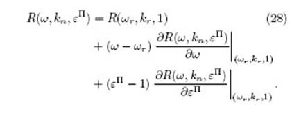
By assuming that _ is small, the equation belowwill be found
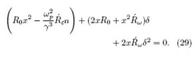
In which,
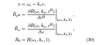
The growth will occur if, the solution of Eq. (29) is imaginary and positive.
Results and discussion
By assuming no beam in the system, the dispersion relation is calculated by solving Eq. (27) numerically. The grating parameters are as follows: R1 = 240 £m, R2 = 400 m, l = 80 m, d = 160 €m, a1 = 400 m, a2 = 480 m and the beam energy is 20 kev, corresponding to the parameters chosen by Y. Zhou et al. 16. The efect of "r on the dispersion relation has been shown in Fig. 2(a). It is clear that increasing the "r results in smaller height of the dispersion relation. This means that the modes are propagating with smaller velocities in the system. The intersection points of beam- wave also move down. In this gure, the corresponding growth rate for each curve is indicated by dash lines (of the same color). Maximum growth rates occur in the vicinity of the synchronous points (€r = krv0), and have the values: 1:279, 1:129 and 1:065 for "r = 1, 1:5 and 2:7, respectively. The in uence of dielectric on the growth rate is clearer in Fig. 2(b), which indicates that dielectrics with higher relative permittivities cause smaller values for the growth rate. The grating parameters are considered in Fig. 3, Fig. 4 and Fig. 5, when"r = 2:7.
In Fig. 3 the slot depth has been changed. As depth increases, the dispersion relation becomes atter, indicating that the efect of grating is increasing. The normalized maximum growth rate happens when resonance between the beam and the modes is possible (the circles). So, in these points = 1:192, 1:066 and 0:493 when h = 100 €m, 160 €m and 250 €m, respectively. Figure 4 indicates how dielectric thickness has an efect on growth rate. Again, lower frequency modes result from increasing dielectric thickness. However, this time the growth rate will increase by this efect: = 0:959, 1:232 and 1:295 for l = 30 €m, 80 m and 110 €m, respectively.
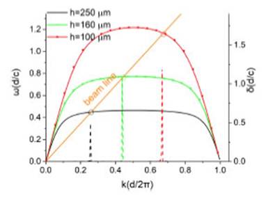
Figure 3: Comparison of dispersion relation for di erent grating heights, when "r = 2:7. The growth rate corresponding to each frequency curve is plotted by dash lines, and maximum values are indicated at the circle points.
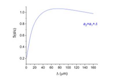
The efect of beam thickness ∆) on growth rate is depicted in Fig. 5. First, increasing ∆ causes the growth rate to rise. Its maximum value is 1:066 at € = 80 €m. This happens because more electrons can participate in the beam wave interaction. Then the growth rate falls. This can be justied by the fact that although the thickness is increasing, the electrons which are far from the grating contribute less to the interaction.
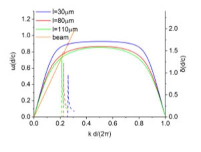
Figure 4: Comparison of the dispersion relations (solid lines) and the growth rates (dash lines) for diferent thicknesses of the dielectric "r = 2:7.
Conclusions
In this paper, a metallic cylindrical grating lled with a dielectric is proposed. The dispersion relation of the modes propagating in this con guration with an annular electron beam is derived. It is shown that the dielectric causes modes with smaller frequencies, in comparison with results when it is absent. Then, the growth rate of modes which are in resonance with the beam is considered. It is found that the growth rate is under the influence of dielectric relative permittivity "r, the depth of the slots of the grating and the thickness of the dielectric (the width of the slots). A lower growth rate is the result of increasing the parameters of the dielectric relative permittivity and slot depth, and decreasing the thickness of the dielectric. Also, beam thickness can increase and de- crease the growth rate, depending on its amount. As we can see, by changing the grating parameters, as well as dielectric permittivity and thick- ness, the growth rate and operating frequencies of the device can be controlled. So, it is possible to make SP-FELs with the desired frequencies and powers. These results can be of considerable interest for THz wave source research.

