


Servicios Personalizados
Revista

Articulo
 Inglés (pdf)
 Articulo en XML
 Referencias del artículo
 Enviar articulo por email
Indicadores
-
 Citado por SciELO
Links relacionados
-
 Similares en
SciELO
Similares en
SciELO
Compartir

 Permalink
Papers in physics
versión On-line ISSN 1852-4249
Pap. Phys. vol.8 no.2 La Plata dic. 2016
http://dx.doi.org/10.4279/PIR080007
Knife-bladed vortices in non-Newtonian fluids
E. Freyssingeas,1 D. Frelat,1 Y. Dossmann,1 J.-C. Géminard1*
*E-mail: jean-christophe.geminard@ens-lyon.fr
1 Univ Lyon, Ens de Lyon, Univ Claude Bernard, CNRS, Laboratoire de Physique, F-69342 Lyon, France.
Received: 1 July2016, Accepted: 24 October 2016
Edited by: J. P. Hulin
Reviewed by: C. Nouar, LEMTA, Université de Lorraine, Nancy, France.
Licence: Creative Commons Attribution 3.0
DOI: http://dx.doi.org/10.4279/PIR080007
Abstract
A tank is filled with a non-Newtonian fluid. We report on the deformation of the free surface resulting from the presence of an underlying vortex. In a tiny range of the experimental parameters, the flow spontaneously loses its initial axisymmetry, leading to the formation of a stationary knife-bladed vortex. We report on the series of patterns observed experimentally and summarize the conditions of the existence of the latter by establishing a state diagram.
Keywords Vorticity, Non-Newtonian Fluid
I. Introduction
Flows in complex fluids exhibit many intriguing phe-nomena [1]. Among them, one of the most striking is the appearance of a cusp at the trailing end of a bub-ble rising through a non-Newtonian, viscoelastic fluid [2, 3]. Interestingly, the cusp assumes a knife-edge shape which is the result of an instability leading to spontaneous symmetry breaking of the interface. Such symmetry breaking, which is forbidden in Newtonian fluids and thus only possible due to the non-Newtonian properties of the fluid, has also been revealed observing the deformation of the free surface resulting from the settling of a solid sphere [4, 5]. Symmetry breaking has also recently been observed in a jet of a visco-elastic fluid impinging on a wall at right angle [6]. Follow-ing the same research line, we were seeking for an experimental situation involving the free surface, making possible to observe a spontaneous loss of axi-symmetry in a configuration similar to that in Ref. [4], but in the steady state. We came to the idea of producing a vortex in a complex fluid and observing that the free surface was an adequate and convenient experimental configuration to achieve.
Conversely to vortices in Newtonian fluids, vortices in complex fluids, and specially the resulting deforma-tion of the free surface, have attracted little or no atten-tion. However, we mention here a recent study of the formation of vortices in non-Newtonian fluids [7]. One can notice that, in many practical cases, complex fluids, such as viscoelastic fluids (e.g., polymers or wormlike micelles solutions) or yield-stress fluids (e.g., gels or foams), are set in rotation, leading to the formation of vortices in the bulk and to the deformation of the free surface. Our aim is thus to provide a first experimental study of the deformation of the free surface of a non-Newtonian fluid and to show that, in a tiny range of the experimental parameters, one can indeed observe a spontaneous loss of the flow symmetry (Fig. 1). To do so, we first characterize the fluids in use and then report a series of experimental observations; among them, the state diagrams and some geometrical characteristics of the observed patterns.
II. Setup and protocol
We aim at characterizing at best, using simple imaging techniques, the deformation of the free surface of a non-Newtonian fluid due to the presence of an underly-ing vortex. We first describe the experimental device, then the fluids under study and finally, the experimental protocol.
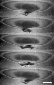
Figure 1: Asymmetric vortex observed at the free surface of a non-Newtonian fluid. The free surface is observed from below. One clearly observes that the vortex lost the initial symmetry and exhibits two tips. The scalebar is worth 1 cm (Camera 3, Ω = 4.5 Hz, h = 4 cm, sample 1). Associated movies Fig.1.avi, Fig.1.c1.avi, Fig.1.c2.avi, and Fig.1.c4.avi can be found as supplementary material [8].
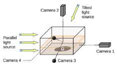
Figure 2: Sketch of the experimental device. The cameras 2, 3 and 4 are in the same vertical plane, perpendicular to the axis of camera 1. Depending on the ob-servation angle, either of the two light sources is used. The horizontal size of the container is 20×20 cm2, and its depth is 10 cm.
i. Experimental device
The main part of the experimental device (Fig. 2) con-sists of a square tank (in-plane size 20×20 cm2, depth 10 cm). The side walls are made of glass plates, whereas the bottom is made of a thick PVC (Polyvinyl chloride) plate. A cylindrical housing, machined in the bottom, receives a PVC disc (diameter 10.1 cm) whose surface is flush with the bottom of the tank. The disk is driven in rotation by a DC motor fed by a power supply, so that the rotation velocity can be tuned in the range from 0 to 6.25 Hz. Flat side walls avoid optical defor-mations when observing from side. The lateral dimen-sions of the base have been chosen to ensure that, in our experimental conditions, the fluid flow never spatially extends to the lateral walls so that the observed patterns are not altered by lateral boundary conditions.
Our experiments rely on visual characterization of the deformation of the free surface. We use 2 CCD cameras (Jai, CB-080; COSMICAR TV Zoom Lens 12.5- 75mm, 1:18) to quantitatively assess geometrical prop-erties of the free surface. These two cameras (Camera 1 and Camera 2) are set in front and above the tank respectively, to make it possible to visualize the vertical and in-plane profiles of the free surface. Both CCD cameras provide accurate images, easy to ana-lyze. We also use 2 additional cameras (Webcams, Log-itech Quickcam Pro 9000) to report qualitative observa-tions. These two webcams (Camera 3 and Camera 4) are placed one above and the second below the free sur-face plane. They both point toward the center of the free surface, making angles of about 30 deg and 20 deg with the horizontal. Cameras 2, 3 and 4 are all in the same vertical plane, perpendicular to the axis of Camera 1. In order to assess the vertical profile from the front view (Camera 1), the fluid is lit with a parallel, horizontal white light, which casts the shadow of the free surface onto a sheet of tracing paper covering the output side wall. Cameras 2, 3 and 4 are used with light from a sec-ond white source which provides parallel light, making a 45-degrees angle with the vertical.
ii. Fluid samples
The yield-stress fluids in use are mixtures of various concentrations of a commercial hair gel (Styling gel extra strong fixing, Auchan production, mainly made up of Carbopol1) and distilled water. The rheological properties of such mixtures do not allow us to generate vortices in too concentrated mixtures (typically over 50 wt.% in gel). We therefore considered only mixtures with concentrations in hair gel smaller than 50 wt.%.
Figure 3: Shear viscosity η vs. shear-stress σ (Sam-ple 3).
To prepare these mixtures, chosen masses of gel and distilled water are mixed in a large container (1 to 3 liters of fluid are necessary for the experiments), and then stirred for several minutes. The mixture is then let to rest at room temperature for at least 12 hours for good homogenization. Then, to get rid of air bubbles in the mixture that could prevent correct visualization, the mixtures are centrifuged at 1100 rpm for 5 minutes.
We used two different batches of hair gel which, al-though of the same brand, have slightly different rheo-logical properties. Batch 1 exhibits a yield stress larger than batch 2. We mainly focused our investigation on four different mixtures: 45 wt.% and 40 wt.% of gel from batch 1 and 45 wt.% and 35 wt.% from batch 2 in water. A fifth mixture, 20 wt.% of gel from batch 1 was studied at a single height (4.3 cm). Samples are numbered and labeled according to Table 1.
We assessed rheological properties of the samples us-ing a rheometer (Bohlin; C-VOR 150) in plane-plane geometry (plate diameters: 60 mm) at room tempera-ture (22◦C). In order to avoid sliding at the walls, sand-paper was glued on both surfaces. In order to insure re-liable measurements, we considered two different gaps, i.e., 1 mm and 0.5 mm, between the plates and checked that the results were similar for both gaps. We report averages over 3 measurements.
The viscosity r¡ was obtained by measuring the shear-rate at constant imposed shear-stress, <r (Fig. 3). One observes two regimes. For small o-, data are very scat-tered: the imposed shear stress is below the yield, Le., the torque applied by the rheometer is not enough to make the fluid flow. In contrast, beyond a threshold shear stress, <tq, the applied torque induces a contin-uous flow. The viscous behavior of the flow is dom-inant. We remark that the measurements do not re-veal any significant hysteresis upon increasing and de-creasing shear stress (or equivalently shear rate) in this regime. Above the yield, the viscosity decreases when <t is increased, according to r¡(i) oc o-"15. We have r¡(l) > r¡{2) > r¡(3) > r¡(4) > r¡{5) (Fig. 4a). In addition, the storage modulus G' was obtained by imposing a periodic shear-stress at 1 Hz and by measuring the resulting shear-strain (Fig. 4b). Again, two regimes are observed. For small o-, the measurements exhibit a plateau while, beyond a threshold shear-stress, the storage modulus G' decreases when the shear stress is increased. Note that the valúes of the yield stress are very similar to those obtained above, from the measure-ment of the viscosity. In this regime, G' oc o-"15 and G'(l) > G'(2) > G'(3) > G'(4) > G'(5). From these two experiments, we assess that all samples exhibit a well-defined yield stress, <tq (Table 1). Samples 1 and 2 have similar rheological behaviors, r¡{\) and r¡{2), G'(l) and G'(2) as well as o"o(l) and ero(2) being of the same order of magnitude. Samples 3, 4 and 5 are much less viscous and elastic, with smaller valúes of the yield stress than samples 1 and 2.
iii. Experimental protocol
The chosen fluid is poured in the tank and leveled to a chosen height, h. The central disc is set in rotation. The rotation velocity, O, is increased by steps up to the máximum rotation velocity of about 6 Hz and, then, de-creased still by steps until rest. At each step, we record movies from the various cameras in the steady-state.
III. Experimental results
i. Control experiment in a Newtonian fluid
We first report on a control experiment performed with a Newtonian fluid (a water/glycerine mixture) to valídate the experimental set-up. The free surface exhibits a parabolic shape and deepens when the rotation velocity O is increased. The máximum depth of the profile, D, increases linearly with Ω2, for limited values of Ω (Fig. 5). This behavior is in accordance with the predic-tion for a Newtonian flow in solid body rotation. When the rotation velocity is further increased, the vertical ex-tent of the central depression is restricted by the bottom of the tank. No hysteresis is observed upon increasing and decreasing.
ii. First experimental observations in weakly non-Newtonian fluids
Let us first consider the behavior of the free surface for samples which exhibit rather small storage modulus G0 (Samples 3, 4 and 5, Table 1). Upon increasing the rotation velocity , above a threshold, which depends on the depth h, a depression appears at the vertical of the rotating disk (Fig. 6). Initially, the deformation is concave. But, upon increasing, one observes the appearance of shapes involving a change in the sign of the curvature of the profile (Fig. 6, 3:55 Hz). One can immediately notice from the images that the geometry of the free surface is mainly governed by geometrical constraints. We report in Fig. 7 a summary of the main geometrical characteristics of the observed deformation of the free surface as function of . We focus on three dierent characteris-
ii. First experimental observations in weakly non-Newtonian fluids
Let us first consider the behavior of the free surface for samples which exhibit rather small storage modulus G' (Samples 3, 4 and 5, Table 1).
Upon increasing the rotation velocity Q, abo ve a threshold, which depends on the depth h, a depression appears at the vertical of the rotating disk (Fig. 6). Ini-tially, the deformation is concave. But, upon increasing Q, one observes the appearance of shapes involv-ing a change in the sign of the curvature of the profile (Fig. 6, Q > 3.55 Hz). One can immediately notice from the images that the geometry of the free surface is mainly governed by geometrical constraints. We report in Fig. 7 a summary of the main geometrical character-istics of the observed deformation of the free surface as function of Q. We focus on three diíferent characteristics: the depth D, i.e., the distance between the lowest point of the profile and the free surface; the width W, i.e., the typical diameter of the depression at the free surface; the width Wi, i.e., the typical distance between the inflection points in the profile from camera 1. On the one hand, the lateral size of the depression, W or Wi, is of the order of the diameter of the rotating disk. Hence, we observe that the fluid can only be set in motion above the rotating disk. The fluid motion is thus confined in a vertical column having a diameter of about the diameter of the disk. The remaining volume of fluid in the tank remains at rest. On the other hand, the flow extends to the free surface only if Ω is large enough. Upon fur-ther increase of Ω, the depth D of the depression at the free surface is rapidly limited by the depth of fluid, h. At large Ω, the bottom of the depression is flat. Note, however, that the disk is never dewetted and a thin layer of fluid remains at center. In this conditions, the profile of the free surface exhibits a significant hysteresis. Indeed, upon decreasing Ω, one observes that the bot-tom of the depression progressively detaches from the bottom of the container but that the central part, that is in solid body rotation, remains flat and horizontal. The depth D decreases until it vanishes.
We finally mention that the crater can lose axi-symmetry and exhibit polygonal shapes like smoke rings [9, 10], liquid tori levitating due to Leidenfrost effect [11], hydraulic jumps [12, 13] or simple liquids in the same experimental conditions as ours [14, 15]. Vortex rings and their stability have attracted much at-tention in the past [16] and we will not develop further the case of weakly non-Newtonian fluids, but rather fo-cus on the behavior of the free surface in the case of strongly non-linear fluids. We shall see that the free surface can then loose its initial axi-symmetry due to a qualitatively different physical mechanism.
iii. Strongly non-Newtonian fluids
The samples 1 and 2 exhibit similar rheological proper-ties and, in accordance, the behavior of the free surface is very similar in both fluids. In addition, in spite of a slight hysteresis, the system exhibits similar behaviors for increasing and decreasing rotation velocities. Ex-ploring a large range of height, h, and increasing rota-tion velocity Ω, we report for sample 1, the set of 5 typ-ical shapes of the free surface in the steady-state that we managed to observe experimentally.
a. Bulge
For small rotation velocity Ω, we observe an axi-symmetric bulge above the disk at the center (Fig. 8). Around this bulge, the fluid is at rest, as can be directly deduced from the roughness of the surface, which re-mains static. In the central region, the fluid of the free surface is in solid body rotation, as can be proven by marking the surface with a tool and observing that this mark remains unchanged. The rotation velocity at the surface, ω, which is always smaller than the rotation velocity of the disk, Ω, decreases when the depth h is increased. We observe that, initially, the height of the bulge increases when Ω is increased.
b. Cap
At a slightly larger rotation velocity Ω, a circular cap pops up at the center of the bulge (Fig. 9). The tran-sition depends slightly on the depth of fluid, the criti-cal rotation velocity increasing almost linearly with h (see state diagram in Fig. 13). In this regime, the fluid around the bulge is still at rest, the cap at the center is in solid-body rotation, but the free surface in the remain-ing part of the bulge flows. The rotation velocity of the cap is always smaller than that of the bulge in the central region. As Ω is further increased, the bulge flattens while the height of the cap above the free surface de-creases (from 7-8 mm at the lowest velocities, down to about 2 mm). Meanwhile, the diameter of the cap is of about 2 cm in diameter, almost independent of Ω, for small h (typically less than 3.5 cm). We note however a slight decrease of its lateral size when Ω is increased for larger h. These behaviors are reversible. We note that a further increase of Ω leads to the appearance of a depression around the cap.
c. Crater
When Ω is further increased, the cap sinks below the free surface. We observe the formation of a crater (Fig. 10), at the bottom of which the cap remains, at least close to the transition which is discontinuous. In-deed, the center of the free surface suddenly sinks from several millimeters (Fig. 12). The onset increases with h (see state diagram in Fig. 13). The depth of the crater increases with Ω. By contrast, the diameter of the crater at the top (typically 4-6 cm) does not depend significantly on Ω but decreases when h is increased. Depending on h, we observe two scenarios. For small height h (typically smaller than 3 cm), the center of the crater remains circular at any rotation velocities and its diameter decreases when Ω is increased. By contrast, for larger height h (typically above 3 3.5 cm), as the rotation velocity increases, the central part of the crater loses its original circular symmetry for taking an oval shape. The cap becomes increasingly asymmetric when Ω is increased; the size of the major axis always remains constant while the size of the minor axis decreases pro-gressively. In this case, a further increase of Ω leads successively to two more states of the free surface, both asymmetric, that we describe in the next sections.
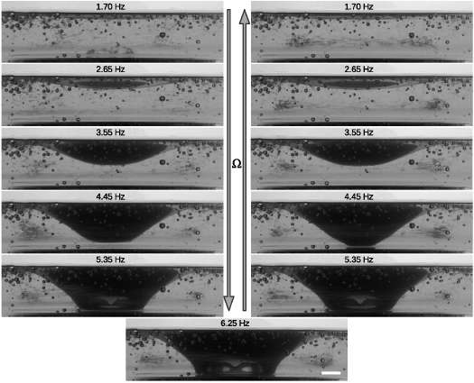
Figure 6: Evolution of the free surface profile upon increasing rotation velocity, Ω. Note that the profile exhibits significant hysteresis when Ω is cycled. The scalebar is worth 1 cm (Camera 1, h = 2.4 cm, sample 3).
d. Knife-edge
When the cap at the center of the crater is reduced only to a furrow, the bottom of the depression sinks in and takes the form of a twisted knife-edge that rotates around the vertical axis (see Fig. 1). One thus notice the occurrence of a furrow (with forks at both ends). The transition seems to be continuous; the circular shape of the negative cap turning, gradually, into a furrow that sinks into the gel. The rotation velocity of the knife-edge, ω, is again much smaller than that of the rotating disc, Ω. Its length, W, and depth, D, depend on Ω; in particular, W decreases when Ω is increased. Note that the obtention of this steady knife-edge, equivalent to that observed in Ref. [4], constitutes the main achieve-ment of our experimental study. It is observed in a very narrrow range of the experimental parameters as can be seen in the state diagram reported in Fig. 13.
e. Singular point
Finally, when Ω is further increased, the length of the knife-edge, W, decreases until it vanishes. The latter then reduces to a single point (Fig. 11). The transition between the knife edge and the singular point is again continuous. Note that the surface is still not tates around the vertical axis with a rotation velocity axi-symmetric but takes the shape of an inverted and smaller than that of the disc. Its typical size does signif-slightly twisted triangular-based pyramid. The latter roicantly depend on Ω.
iv. State diagram
We have qualitatively distinguished 5 typical shapes of the free surface. We report, in Fig. 12, an example of the evolution of the characteristics of the pattern at the free surface as function of the rotation velocity Ω for a given depth of the fluid bed.
In order to go further, we propose, in Fig. 13, state diagrams where the various patterns are located in the plane (h,Ω). As only little hysteresis is observed be-tween increasing and decreasing Ω, we report data for increasing rotation velocity, only. We note that the knife-edge is seen in a narrow región at intermedíate rotation velocity O for sufficiently large depth h of the fluid bath. In order to account for the effect of the fluid proporties, we report diagrams for samples 1 and 2 (Ta-ble 1). Sample 2 exhibits a slightly smaller storage modulus G' than sample 1. As a consequence, the do-mains of the knige-edge (a) and of the singular point (d) are slightly shifted toward larger depth, h, and thus slightly reduced, compared to what was observed for sample 1.
IV. Discussion
In this section, we qualitatively explain the origin of the observed patterns. From images from side, on can have a clue on the structure of the flow in the material (Fig. 14).
First, due to the non-sliding condition at the disk sur-face, a rotation of the fluid with the orthoradial veloc-ity r Ω is imposed at the bottom of the fluid bed above the disk (r is the radial coordinate). The fluid enters in motion in the radial direction if the associated stress ρ (r Ω)2 exceeds the yield stress σ0. Denoting R the ra-dius of the rotating disk, we can define a minimal rotation velocity Om = ^cr0/p/R below which the fluid, in the vicinity of the disk surface, does not flow in the radial direction (p denotes the density of the fluid). From the experimental valúes of <tq, p and R, we estímate Om = (0.3 + 0.1) Hz, depending of the sample. The latter valué is compatible with the lower bound of the rotation velocity range in which we observed deforma-tion of the free surface.
Once the radial flow is initiated, it extends away from the disks over a distance again limited by the yield stress, <tq. Considering the orthoradial velocity R O imposed at the edge of the rotating disk, assum-ing that the flow extends over the distance L, we can write that the viscous stress, r/RQ/L, is constant and equals the yield, the condition being imposed by the fact that at R + L the fluid remains at rest. We get L = t]RQ/<to. Here, r¡ takes the valué measure for cr - <tq (Fig. 4). For instance, considering the most rigid fluid, with <tq ~ 800 Pa, we estímate r¡ ~ 50 Pa.s and, thus, L ~ 2 cm for O ~ 1 Hz. This valué is again compatible with the observed radial extensión of the roll observed in Fig. 14.
Thus far, we have showed that the rotation of the disk puts the fluid in radial motion in a región of typical di-ameter 2(R + L) in the disk plañe. In turn, this outward flow has a pumping effect, Le., fluid flows back above the disk as can be seen in Fig. 14 and rolls form. Their typical vertical extensión is imposed by the geometrical constraints so that it is of the order of a fraction of the radius of the disk, R. We assume here that the depth, h, of the fluid bed does not limit the flow which thus does no extend to the free surface. In this limit of deep fluid beds, we predict that the fluid remains at rest around the disk, at a radial distance larger that R + L, and above the disk, at a distance of about aR, with a < 1. The región above the disk, in which the fluid is in motion, is thus separated from the rest of the fluid which remains at rest by a horizontal shear band which clearly visible in Fig. 14. The thickness, T, of the shear band is such that the shear stress equals the yield and we get, follow-ing the same reasoning as above, that T ~ L/2 ~ 1 cm, in agreement with the observations.
From this analysis of the underlying rolls, we can qualitatively understand the sequence of the patterns we observe experimentally. Note first that, in our experimental conditions, the depth of the fluid bed, h, is al-ways limited, smaller than R so that the rolls can reach the free surface. Upon increasing O, one observes the following sequence of patterns:
. Very small O, typically smaller than Q.m - The ro-tation velocity is so small that it does not induce any radial flow. No pattern is observed.
. Rotation velocity O > Om - The rotation velocity is large enough to induce a radial flow, but only in a limited región of the disk. Indeed, the radial stress induced by the rotation overcomes the yield stress for r > rm =¡ ^cr0/p/Q., only. As a con-sequence, rolls form but their typical radial size is of the order of R - rm. Accordingly, their typical vertical size is of about a(R - rm). Thus, because of the solid-like behavior of the material below the yield, a layer seats at rest on top of them. However, the inward flow at the top of the rolls produces an inward creep of the material above, leading to the formation of the bulge.
. Rotation velocity O > Q/¡, such that the rolls reach the free surface - Due to the toroidal shape of the rolls, the outer flow lines form a cusp at center. In this región, above the cusp, the material does not flow but, again due to the inward stress, the creep leads to the formation of the cap, Le., a volume of fluid in solid body rotation surrounded by flow-ing material. Considering that the top of the rolls reaches the free surface when a(R-rm) = h, we get Qh = a/co/p -§-r. Typically, we get a valué of Q/¡ that is of the order of a few Hz for the most rigid fluid and increases with h. In spite of a quantitative discrepancy, the transition is correctly predicted by this argument.
. For modérate valúes of O above Q/¡, the horizontal stress cr (Fig. 14) exerted by the rolls on the fluid sitting on top still makes the free surface rise. But, conversely, when O is further increased, the increase of the vertical component of cr at the center, which is oriented downward, overcomes the inward radial contribution, which leads to a downward displacement of the free surface. We oberve what we called the 'negative' cap. Indeed, even in this case, a volume of the fluid can remain in solid body rotation at the center. This transition is dif-flcult to predict quantitatively without the knowledge of the structure of the rolls, but the transition is qualitatively well understood.
. Finally, further increase of the rotation velocity leads to the erosión of the domain of fluid in solid rotation at the center. When it disappears, we observe either the knife-edge or the singular point. The transition is again difficult to predict precisely but we can estímate the máximum valué of the vertical component of the velocity in the roll around, vm, which is compatible with no flow at center. To do so, we write that, at the external edge of the central column of fluid, the shear stress, r¡ vm/(2R), is of about the yield stress <tq. Assuming further that vm is of the order of the orthoradial velocity of the fluid at the outer egde of the disk RÍIm, we estímate this central región which remains in solid body rotation disappears for Q.m > 6 Hz. This valué is compatible, in order of magnitude, with the velocity measured at the transition between the cap and the knife-edge for the deepest fluid beds (Fig. 13). Note, however, that the dependence on h is not accounted for by our argument, which would require the introduction of a precise description of the rolls to account for the details of the transition.
Finally, we remark that, even if we qualitatively understand why the cap, submitted to the compressive stress cr, can buckle and lose the axi-symmetry, we are not able to describe the knife-edge and the singular point. The description of these speciflc patterns in detail deserves a special theoretical effort.
V. Conclusion
We carried out an experimental investigation of the de-formation of the free surface of a complex fluid induced by an underlying vortex. We observe, upon increasing rotation velocity Ω, a sequence of patterns that we de-scribed and understood, at least qualitatively, by con-sidering the main characteristics of the underlying vor-tex. We reported a state diagram in which the domains of observation of the various patterns are placed in the plane rotation velocity - depth of the fluid bed, (Ω - h).
The main achievement of our study is the observation of the knife-edge and of the singular point that are very specific patterns that would not be observed in Newto-nian fluids. They are the steady-state version of the pre-viously observed folding of the free surface of a com-plex fluid during the penetration of a sinking bead [4]. Our experimental configuration is particularly interest-ing as it makes possible the observation of patterns in the steady state whereas the previous experiments only gave access to transients.
However, the present study remains purely qualita-tive and thereby raises several theoretical points. First, a better description of the fluid flow, including a precise account of the fluid rheology, would be necessary for a precise description of the state diagrams. But, in addition, the experimental configuration is interesting to answer several questions: are the patterns of the free surface observed in this investigation generic to the non-Newtonian fluids or for yield stress fluids only? Are the same types of patterns observed for a viscoelastic fluid (entangled solutions of polymers or wormlike mi-celles)? The applications of such a study are numerous, especially in terms of geophysics, where complex fluids play an important role (landslides, lava flow).
1. P Coussot, Yield stress fluid flows: A review of experimental data, J. Non-Newton. Fluid 211, 31 (2014). [ Links ]
2. D De Kee, R P Chhabra, A photographic study of shapes of bubbles and coalescence in Non-Newtonian polymer solutions, Rheol. Acta 27, 656 (1988). [ Links ]
3. N Dubash, I A Frigaard, Propagation and stopping of air bubbles in Carbopol solutions, J. Non-Newton. Fluid 142, 123 (2007). [ Links ]
4. T Podgorski, A Belmonte, Surface folds during the penetration of a viscoelastic fluid by a sphere, J. Fluid Mech. 460, 337 (2002). [ Links ]
5. T Podgorski, A Belmonte, Surface folding of viscoelastic fluids: Finite elasticity membrane model, Eur. J. Appl. Math. 15, 385 (2004). [ Links ]
6. H Lhuissier, B Neel, L Limat, Viscoelasticity breaks the symmetry of impacting jets, Phys. Rev. Lett. 113, 194502 (2014). [ Links ]
7. C Palacios-Morales, R Zenit, The formation of vortex rings in shear-thinning liquids, J. Non-Newton. Fluid 194, 1 (2013). [ Links ]
8. Supplementary material can be found at http://dx.doi.org/10.4279/PIP.080007 [ Links ]
9. R H Hernandez, B Cibert, C Bechet, Experiments with vortex rings in air, Europhys. Lett. 75, 743 (2006).
10. I S Sullivan, J J Niemela, R E Hershberger, D Bol-ster, R J Donnell, Dynamics of thin vortex rings, J. Fluid Mech. 609, 319 (2008).
11. S Perrard, Y Couder, E Fort, L Limat, Leidenfrost levitated liquid tori, Europhys. Lett. 100, 54006 (2012).
12. T Bohr, C Ellegaard, A Espe Hansen, A Haan-ing, Hydraulic jumps, flow separation and wave breaking: An experimental study, Physica B 228, 1 (1996).
13. A Andersen, T Bohr, T Schnipper, Separation vor-tices and pattern formation, Theor. Comp. Fluid Dyn. 24, 329 (2010).
14. T R N Jansson, M P Haspang, J H Jensen, P Hersen, T Bohr, Polygons on a Rotating Fluid Surface, Phys. Rev. Lett. 96, 174502 (2006).
15. H A Abderrahmane, K Siddiqui, G H Vatistas, Ro-tating waves within a hollow vortex core, Exp. Fluids 50, 677 (2011).
16. K Shariff, A Leonard, Vortex Rings, Annu. Rev. Fluid Mech. 24, 235 (1992).

