


Servicios Personalizados
Revista

Articulo
 Inglés (pdf)
 Articulo en XML
 Referencias del artículo
 Enviar articulo por email
Indicadores
-
 Citado por SciELO
Links relacionados
-
 Similares en
SciELO
Similares en
SciELO
Compartir

 Permalink
Latin American applied research
versión impresa ISSN 0327-0793
Lat. Am. appl. res. v.38 n.2 Bahía Blanca abr. 2008
A quasi-coulomb model for frictional contact interfaces. Application to metal forming simulations.
C. Garcia Garino1 and J.-P. Ponthot2
1 Instituto Tecnológico Universitario, UNCuyo Casilla de Correo 947, 5500, Mendoza, Argentina
cgarcia@itu.uncu.edu.ar
2 LTAS - Milieux Continus & Thermomécanique Université de Liége, B-4000 Liége, Belgium
jp.ponthot@ulg.ac.be
Abstract — Frictional contact interfaces have to be modeled in practice when industrial problems such as metal forming operations, crashworthiness, and so on, have to be simulated. Usually a Coulomb model is used in order to describe the constitutive law for the frictional case. Following a standard non associated plasticity approach to Coulomb law a non-symmetric tangent operator results, and so a non-symmetric solver has to be used in order to take full advantage of consistent operators. With respect to symmetric ones, these non-symmetric operators lead to prohibitive computational times. However, in practice different schemes have been proposed in order to recover the symmetric operator, and consequently, use a symmetric solver. In this work an alternative approach based on an idea due to García Garino and Oliver (1992) is defined in order to avoid to deal with non-symmetric solvers and thus save a large amount of computational time, which renders the computational simulation more attractive to industry. Applications to metal forming simulations and crashworthiness analysis are considered.
Keywords — Friction; Contact; Plasticity; Large Deformations; Metal Forming.
I. INTRODUCTION
The Finite Element Method (Zienkiewicz and Taylor, 1989; Bathe, 1996) can be considered as a valuable tool in order to simulate large industrial applications. In the last few years very important progress has been reported in the simulation of non linear problems involving plasticity, large strains and metal forming simulations, as can be seen in the proceedings of Computational Plasticity (Owen et al., 1987, 1989, 1992, 1995, 1997) or NUMIFORM conferences (Thomson et al., 1989; Chenot et al., 1992; Shen and Dawson, 1995 and Huetink and Baaijens, 1998). In many cases the simulation of manufacturing processes like metal forming requires to take into account, besides non linear constitutive models, complex boundary conditions like frictional contact behavior (Huetink and Baaijens, 1998; Chen and Kikuchi, 1985; Wriggers and Vu Van, 1990). Another important field of research where this kind of interfaces are required is Crashworthiness analysis.
The contact problem involves the interface of two deformable bodies or a deformable body against a rigid tool (unilateral contact). In both cases one body is prevented from penetrating the other. Consequently the possible configuration and displacement fields are constrained in the admissible values to be reached.
From the mathematical point of view, the mechanical problem stated in the previous paragraph can be considered like an optimization problem and several methods can be found in the literature: Penalty method (Ponthot and Graillet, 1999; Hallquist, 1982, 1986), Lagrange Multipliers (Hughes et al., 1976; Bathe and Chaudary, 1985, 1986) and Perturbed La-grange Formulations (Simo et al., 1985), from which the two others method can be derived, and Augmented Lagrangian formulations. (Wriggers et al., 1985; Simo and Laursen, 1992; Laursen and Simo, 1993).
The frictional behavior is usually taken into account in Computational Mechanics by mean of elastoplasticity analogy (Curnier, 1984), and in the last years Wriggers and coauthors (Wriggers, 1987; Wriggers and Vu Van, 1990) have derived very efcient numerical tools, extending the Radial Return algorithm to this context. A review of the subject can be found, among others, in Agelet de Saracibar (1990) and Zhong and Mackerle (1992).
The frictional contact problem can be stated enhancing the variational unconstrained problem in order to include the contact and friction contributions. The Finite Element Method leads to write the corresponding discretized problem adding to the Stiffness Matrix K and residual forces R the contact contributions Kc and Rc respectivel y and friction is taken into account by mean of Ff, vector of nodal forces resulting from frictional interactions and Rf respectively. The standard treatment of frictional problem is usually taken into account by using a Coulomb model that leads to a non-symmetric Stiffness matrix. Consequently non-symmetric solvers have to be used in the numerical simulations.
However, recovering a symmetric operator is possible. In that sake, Garcia-Garino and Oliver (1992) and Garca-Garino (1993) proposed an algorithm, called Quasi-Coulomb model, able to integrate the frictional equations in time and that leads to a symmetric tangent operator. Simo and Laursen (1992) and Laursen and Simo (1993) have proposed another idea in order to get a symmetric operator for the contact frictional problem based on Coulomb law.
The capabilities of this new algorithm are analyzed in this paper by solving several large deformation problems pertaining to metal forming simulation and crashworthiness analysis. A penalty formulation and two different large strain elastoplastic numerical models developed by the authors are used (García-Garino, 1993; Ponthot, 1995). The goal of the numerical examples solved is at first sight to discuss the quality of results obtained with the new model in comparison with standard Coulomb law and the to compare the respective computational cost.
A brief discussion in order to highlight differences and similitudes in between Augmented Lagrangian procedure and the proposed model is provided. Both methods relay on a delay of dependence of frictional forces on the contact pressure. However numerical algorithms are completely different. Some commentaries about comparative numerical perfomance is provided when possible.
Anyway, in order to simulate realistic industrial forming simulations, a bulk model is not sufcient and a frictional algorithm has to be implemented. The role of this algorithm is to manage the contact and frictional forces that appear due to material-tools interactions.
The contact algorithms are generally based on a standard plasticity approach (see Curnier, 1984) but with a non-associated flow rule. If one uses an implicit algorithm in order to integrate the motion equations in time, the resulting tangent operator is non-symmetric, due to the non-associated flow rule. This leads to prohibitive computational times.
II. FRICTIONAL CONTACT INTERFACE
A. Governing equations
In many practical problems the boundary conditions have to include the case of frictional contact problems such as the interface between solid and tools. In this case the unconstrained finite strain quasi-static elastoplastic problem written in terms of the internal forces resulting from the straining of the material (i.e. the so-called stress-divergence term resulting from the straining of the material), denoted by G(u) as a function of the nodal displacements u and the external load pattern F results in (see e.g. Zienkiewicz and Taylor (1989) and Bathe (1996) for details):
G(u) − F = 0. (1)
Equation (1) is then enhanced by means of contact and frictional nodal forces respectively denoted by Rc, and Rf to account for contact interactions with tools or other material (see Zong and Mackerle (1992) and the references therein for details). The constrained problem results:
G(u) + Rc(u) + Rf(u) − F =0. (2)
In case of a dynamic problem, inertia forces have to be taken into account. In such a case, the semi-discretized equation to be integrated reads, see Bathe (1996) and Belytschko (1983) for details:
Mü + G(u) + Rc(u) + Rf(u) − F =0, (3)
where M is the mass matrix and ü is the vector of nodal accelerations.
Because of combined geometrical, material and contact non linearities, the systems of Eqns. (2) and (3) are highly non linear in u.The methods of solution of these systems are standard (Bathe, 1996; Belytschko, 1983) and, in numerous cases NewtonRaphson's method has proved to be advantageous.
B. Frictionless contact problem
Attention is now focused on the plane and axisymmetric case of a straight rigid tool boundary x2T − x1T (where T stands for tool), for simplicity. The extension to three dimensional problems is straightforward and all the following formula are valid in 2D, as well as 3D situations.
The constraint equations resulting from contact interactions are based on nodal imposition of the constraint for every slave node pertaining to the boundary of the finite element mesh. In this context, and with reference to figure 1, the gap or penetration is approximated by the finite element method nodally. Here, the gap g, associated with a typical slave node xs is given by:
g = (xs − x1T ) . N, (4)
where N denotes the unit outward normal to the tool segment. Similarly T denotes the unit tangent to this segment. In 3D situations, T defines the local tangent plane to the contact point.
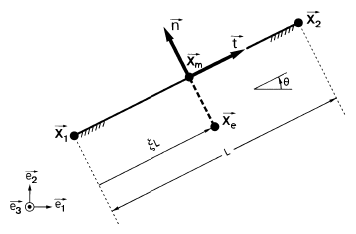
Figure 1: Geometry of the contact problem
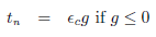
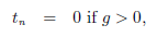
If g is larger than zero, there is no contact interaction between the considered slave node and the segment, and consequently Rc = 0 and Rf = 0 . However, if g ≤ 0, there exists a contact interaction that has to be accounted for, as described hereafter.
The nodal forces Rc arising from contact are computed using the penalty method (Ponthot and Graillet, 1999; Hallquis, 1982; Hallquist, 1986). In local axis the normal contact force tN results in:
 | (5) |
 | (6) |
where  c stands for normal penalty coefcient. This resulting force is written in global coordinates as:
Rc = tN N. (7)
In the case of a rigid flat tool there are no changes in the geometry of the tool from one iteration to another and the contact contribution to the stiffness matrix of the problem, i.e. the derivative of Rc with respect to Δu, the incremental nodal displacement, reads:
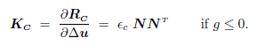 | (8) |
C. Frictional contact problem
In this problem two cases can be distinguished: in early stages of the process, where a full stick condition between the solid and the tool is verified, a tangential force that opposes to the relative slip appears. Once a threshold value in the modulus of the force is reached, a slip condition is verified. This behavior can be modeled by means of the classical Coulomb law:
 | (9) |
and
 | (10) |
where  in case of sticking contact and
  in case of sliding contact. In order to perform a numerical integration of the frictional behavior, we proceed as follows. Starting from a known configuration at time t, one is faced with determining a new equilibrated configuration at time t + Δt. As far as the frictional treatment is concerned, Coulomb's law can be regularized by introducing a penalty factor F. In this way, the problem can be treated similarly to an elastoplastic one, see Curnier (1984). The tangential slip sis thus decomposed into its elastic (reversible) and plastic (irreversible) components
s = se + sp, (11)
so that, by analogy with elasto-plasticity, the constitutive equation for the frictional component can be written, in the tangential plane of contact
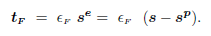 | (12) |
Further, following Wriggers (1987), Wriggers and Vu-Van (1990), an elastic predictor is evaluated first by supposing that the entire incremental slip, resulting from the finite element computation, is totally reversible (elastic). This results in an elastic (sticking) predictor t+Δt tF TR fo r the frictional force given by
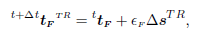 | (13) |
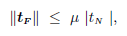
where sTR is the total slip over the increment. This elastic predictor is then compared with the Coulomb criterion (10). If  , the state of contact was clearly a sticking one and nothing more is undertaken. On the contrary, if
  , i.e. Coulomb criterion is violated, the state of contact is sliding and a correction has to be evaluated to restore consistency with the Coulomb criterion. This is done by integrating the following flow rule for the frictional components:
sp = λT. (14)
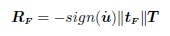
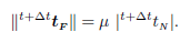
So that, according to (12) the final frictional force will be given by:
 | (15) |
Assuming T =  , an hypothesis consistent with the radial return scheme of elastoplasticity, the norm of (15) can be shown to be:
 | (16) |
The unknown λ is computed by inserting (16) into the Coulomb criterion (10), i.e.
 | (17) |
If the friction coefcient μ is constant the latest equation has a closed form solution and the classical expression of the Coulomb law is recovered:
 | (18) |
Writing the nodal forces 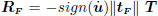 , the frictional contribution to nodal forces and stiffness matrix results (see Wriggers, 1987):
 | (19) |
In the second case, i.e. in the case of sliding contact, Kf is obviously non-symmetric.
To avoid the use of non symmetric solvers, which are computationally much more expensive than symmetric ones, the standard procedure, described above, is modified and the modulus of the normal reaction is no longer updated at each equilibrium iteration. This modulus remains constant all over the load step and equals to the latest converged value. Then the following equation describes a Quasi-Coulomb friction law (García-Garino and Oliver, 1992; García-Garino, 1993) of the type:
 | (20) |
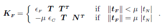
and the discretized Coulomb law (17) can be approximated by:
 | (21) |
I n practice this simplificative assumption is equivalent to approximate in a step wise way the yield function given by equation (10), as can be seen in figure 2.
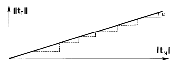
Figure 2: Original (solid line) and modified (dotted line) yield criteria
Remark: the constitutive model proposed in Eq. (20) delays the dependence of friction forces on contact pressure by onetimestep. The assumed value of contact pressure is hold fixed for the complete iteration loop performed for each time step, but it is updated from one time step to another.
It is important to mention that the flow rule is not changed and the problem becomes associated, consequently a symmetric stiffness matrix is obtained. Moreover if the three following conditions are fulfilled:
- i) Elastic-perfectly plastic problem (μ constant).
- ii) A Quasi-Coulomb law is used.
- iii)Linear geometry (rigid tools).
the frictional matrix KF become s trivial,since in this case:
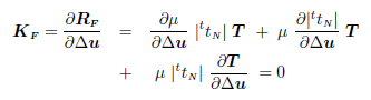 | (22) |
because all the variables are fixed. In this way a symmetric tangent operator is recoverd in a full agreement with the assumption made in the approximation of normal contact pressure.
The numerical implementation of the proposed models preserves the complete structure of the well known penalty method with the condition that contact pressure is hold constant during the iteration loops necessary to reach equilibrium in each time step.
The Augmented Lagrangian procedure is based on two iterative loops: an external augmented loop, when the contact normal pressure is updated and a inner iteration loop that holds contact pressure value fixed. In practice it is very difcult to get the correct choice of the parameters the Augmented Lagrangian algorithm: maximum number of augmentations, strategy about when and how to automatically update the penalty parameters and the Lagrangian multipliers etc. Moreover, the choice of these parameters is very problem-dependent.
Therefore, though the Augmented Lagrangian algorithm seems very attractive at first glance, it is not easy at all to use efciently for complex industrial simulations and generally requires quite a few runs to get a correct answer (a hidden cost that is generally not explained or commented in the papers!). In such cases the algorithm proposed in this study is not only much easier to implement but also much easier to use since it is not more complex to use than the classical penalty algorithm. Morover in this case no new numerical user defined parameter that has to be introduced. From the second's author experience (Graillet et al., 2001 ; Chabrand et al., 2005 ) can be stated that, globally, the cost of Augmented Lagrangian is similar to the cost of the classical penalty algorithm (sometimes, it can be cheaper, but sometimes it can also be more expensive), without taking into account the difculty to tune numerical parameters associated to the Augmented Lagrangian algorithm as already mentioned above.
III. NUMERICAL SIMULATIONS
In order to investigate the effects of the symmetrization process on the accuracy of the results, three benchmarks have been tested. They are presented below. Of course, in case of frictionless problems, this symmetrization process has no influence since the Hessian is already symmetric.
A. Stretching of an axisymmetric sheet with an hemispherical punch
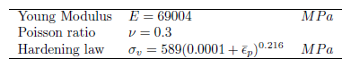
The first example studied is a benchmark problem proposed by Lee et al. (1990) from OSU (Ohio State University). The problem is a sheet forming simulation and consists of the stretching of an axisymmetrical sheet with an hemispherical punch whose geometry is given in Fig. 3. The material is supposed to behave like a J2 elastic-plastic material with non linear isotropic hardening. The material parameters are given in Table 1. This kind of material exhibits a very large hardening rate in the neighborhood of the initial yield stress.
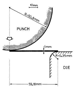
Figure 3: OSU Sheet forming problem: geometry
Table 1: Material properties for the OSU benchmark
The finite element mesh used is a rather coarse finite element mesh as imposed by the benchmark designers. It is shown in figure 4 and consists of 2 layers of 14 elements each. The elements are bilinear and use a constant pressure to avoid locking. Boundary conditions are also shown in Fig. 4. Contact conditions are imposed through a penalty formulation with the following parameters: C = 105N/mm and F = 104N/mm . Three friction coefcients have been considered in the present study, i.e μ = 0.0; μ = 0.15 and μ = 0.30. Many results and comparisons with other authors regarding this problem can be found in the works of García-Garino (1993) and Ponthot (1995). However, we will concentrate here on the Quasi-Coulomb algorithm.
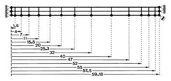
Figure 4: OSU Sheet, forming problem: Initial Finite Element mesh
The comparison of the total force applied by the punch as a function of punch displacement is given in Fig. 5 for μ =0.30 (upper curves) and μ = 0.15 (lower curves) for both classical non-symmetric operator and the symmetric Quasi-Coulomb algorithm presented here. This figure shows an excellent agreement between both algorithms. This agreement in turn proofs the higher efciency of the Quasi-Coulomb algorithm since it only requires a symmetric solver which is much cheaper to use than a non-symmetric one.

Figure 5: Axisymmetric OSU benchmark: Applied punch force as a function of punch displacement. Top: μ = 0.30, bottom μ = 0.15.
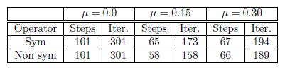
However, using a symmetric operator where the actual tangent operator is non symmetric can affect the rate of convergence of the Newton-Raphson algorithm.
As shown in Table 2, using a symmetric operator only affects moderately this rate of convergence.
Table 2: OSU benchmark. Rate of convergence. μ =0.0
The agreement between Coulomb and Quasi-Coulomb models is not only excellent for the forces (see Fig. 5), but also as far as local values, like the effective plastic strain are concerned (see Figs. 6 and 7). On these figures, the results obtained by the classical Coulomb and the Quasi-Coulomb models are compared. Results obtained by Agelet de Saracibar (1990) are also plotted.
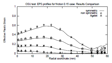
Figure 6: Axisymmetric OSU benchmark. Comparison of plastic strain profile, as a function of initial radius, for punch displacements of 10, 20, 30 and 40 mm. μ =0.15.
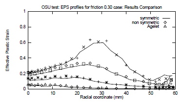
Figure 7: Axisymmetric OSU benchmark. Comparison of plastic strain profile, as a function of initial radius, for punch displacements of 10, 20, 30 and 40 mm. μ = 0.30.
From the obtained results it can be stated that the proposed (symmetric) model compares very well with the (unsymmetrical) Coulomb law: numerical response is practically the same and the number of total equilibrium iterations is similar except for the case of μ=0.15. However computational cost is saved because a symmetric tangent matrix is factorized in this case.
B. Shock absorber device
This second example deals with the numerical modeling of a shock absorber device. It is based on the turning inside-out of a thin walled ductile metal tube. This is generally called an "invertube" device. In this case (Fig. 8), a plain tube is confronted with a hard die to produce the inversion. This inversion, in turn, produces very large plastic strains which form an efcient energy absorbing mechanism during impact. In this way, the kinetic energy of the impacting bodies is dissipated through plastic deformation, in a controlled fashion at an acceptable rate. The yield limit of the material keeps the transmitted force below an acceptable upperbound. Hence, the deceleration is slower and less harmful for the people inside the car.
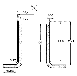
Figure 8: Axisymmetric shock absorber device. All dimensions are in mm. The shaded area is considered to be rigid
Numerical modeling of the collapse of such energy dissipating structures requires not only to take into account the plastic behavior of the tube material, as well as inertial forces, but also to consider very large strains and large amplitude rigid body motions that develop and also, in this case, the accurate prediction of frictional forces. Thus a great number of advanced code capabilities are tested by running this kind of problems.
Similar problems were investigated by Beltran and Goicolea (1989), by Garcia-Garino (1993) with an explicit scheme and by Ponthot and Hogge (1994) who compared the performances of explicit and implicit alalgorithms for impact problems. However, all the previous references dealt with frictionless contact. In the present paper, implicit schemes, as described in the cited work of Ponthot and Hogge (1994) have been used to integrate the equations of motion in time. The initial geometry of the system is given in figure 8.
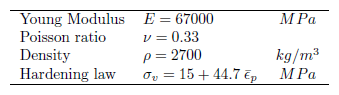
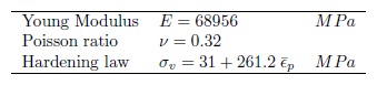
The material consists of an aluminum tube of 50.8 mm outside diameter times 63.5 mm length times 1.63 mm wall thickness. The material is supposed to behave like a J2 elastic-plastic material with linear isotropic hardening. The material parameters are given in Table 3.
Table 3: Material properties for the shock-absorber
The tube has been modeled using 300 quadrilateral elements (3 x 100) with 4 Gauss points and constant pressure to avoid locking. It is driven against a 3.97 mm radius die made of mild steel at a velocity of 44 m/s (144 Km/h). Thus a 50 mm prescribed vertical displacement over a time period of 0.00125 seconds is imposed on the upper nodes of the tube.
The history of the deformation is given in Figs. 9, 10 and 11 for μ = 0, μ = 0.15 and μ = 0.30 cases respectively, and a comparison of the final configurations for the three diferent friction coefcients is given in figure 12. For this simulation, the following penalty parameters have been used: G = 107N/mm and F = 106N/mm.
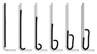
Figure 9: Deformed configurations (frictionless case) for t=0.00, t=0.25, t=0.50, t=0.75, t=1.00 and t=1.25 milliseconds.

Figure 10: Deformed configurations μ =0.15 for t=0.00, t=0.25, t=0.50, t=0.75, t=1.00 and t=1.25 milliseconds.
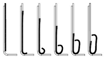
Figure 11: Deformed configurations μ =0.30 for t=0.00, t=0.25, t=0.50, t=0.75, t=1.00 and t=1.25 milliseconds.
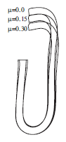
Figure 12: Comparison of the final configurations as a function of the friction coefcient.
In Fig. 13 are displayed the time/load curves obtained for the three coefcients of friction and, in each case, for the classical non-symmetric Coulomb operator as well as the presented symmetric Quasi-Coulomb model. As can be seen on this figure, the proposed algorithm does not affect the results in any significant way. On the other hand from Table 4 follows that the number of total equilibrium iterations is similar in both cases, but for the Quasi-Coulomb model the advantages of a symmetric solver allowed to reduce the computer time by a factor larger than two.
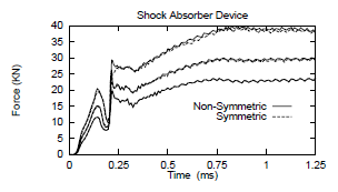
Figure 13: Applied load as a function of time. Upper curves: μ = 0.30; middle curves: μ = 0.15, and lower curve: μ = 0.00
Table 4: Shock absorber device. Rate of convergence.
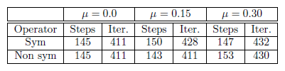
Again, in this case, the obtained results compare very well with the ones computed with the Coulomb law and the number of total equilibrium iterations is similar for both procedures.
C. Conical extrusion
The considered problem is the quasi-static conical extrusion of an aluminum billet. It has been previously studied by Simo and Laursen (1992) and Laursen and Simo (1993). It consists of an initially cylindrical billet (length = 25.4 cm & diameter = 10.16 cm) that is pushed by a ram through a conical rigid die. The total displacement of the die is 17.8 cm and a friction coefficient of 0.1 is assumed between the rigid die and the aluminum. Contact constrains are imposed through the penalty formulation described above. The penalty parameters used are respectively C = 108N/mm and F = 107N/mm. The aluminium is supposed to behave like a J2 elastic-plastic material with linear isotropic hardening whose material properties are given in Table 5.
Table 5: Material properties for the conical extrusion
The initial mesh consists of 80 (4x20) axisymmetric bilinear elements with constant pressure. The initial configuration, as well as deformed configurations corresponding to a ram displacement of 4.45 cm; 8.9 cm; 13.5 cm and 17.8 cm are depicted in figure 14. In the final configuration, the cumulated slip of the first contact node is larger than 25 cm whereas the maximum penetration due to the penalty treatment is smaller
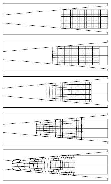
Figure 14: Initial mesh and deformed configurations for a ram displacements of 4.45 cm; 8.9 cm; 13.5 cm and 17.8 cm
The force applied by the ram as a function of ram displacement is plotted in figure 15. The results obtained by Simo and Laursen (1992) and Laursen and Simo (1993) are also plotted. The results for both operators are identical until a ram displacement of 12 cm. After that, the friction force increases exponentially and the force obtained with a symmetric operator exhibits a small "delay" with respect to the non symmetric one. This delay is due to the extreme variation of the normal force. The difference is originated in the fact that the friction force is computed with respect to the previous converged normal force and not the current one. Such an extreme variation shows the limitations of the proposed algorithm. This distance between the two curves could be canceled out by using smaller time steps in the symmetric case. However, doing so would annihilate the benefits of the proposed methodology.
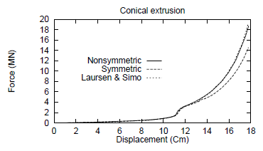
Figure 15: Conical extrusion process: Force applied by the ram as a function of its displacement.
The final configuration was obtained in 115 time steps and 264 iterations for the classical non-symmetric operator and in 136 time steps and 348 iterations for the Quasi-Coulomb symmetric operator. However, the CPU is still 25% lower in the latter case. It is difcult to compare the total computational cost with the Augmented Lagrangian proposed by Simo and Laursen (1992) and Laursen and Simo (1993) procedure because in their papers only the total number of time steps and augmentations are provided, but no information is given about the number of iterations performed. However a qualitative comparison can be found in Ponthot's Thesis (1995).
IV. CONCLUSIONS
A very simple constitutive frictional model which is able to deal with both general large strain plasticity problems, as well as specialized ones such as sheet metal forming problems and crashworthiness has been presented and tested. This model is very easy to code in any non linear general purpose finite element, or finite difference code and there is no new numerical parameter introduced. A symmetric tangent operator is obtained in a fully consistent way the assumption made in the approximation of normal contact pres-sure, hold fixed for the complete time step and equals to the last converged value.
In problems when thin bodies are simulated, like the sheet forming operation and to a dynamic shock absorber device simulation, the proposed quasi-Coulomb algorithm presented here shown the same results than standard procedure. Morover, total number of iterations are similar for proposed Quasi-Coulomb and classical Coulomb laws. Consequently large amounts of computational time can be saved, because the proposed procedure allows to use a much cheaper symmetric solver rather than an expensive non-symmetric one, a feature which is very important for industrial applications.
In the case of conical extrusion, the extreme variations of the forces encountered prevent a totally successful application of the proposed algorithm and a carefull study of obtained results are advised for bulk forming cases. However, this kind of situation does not prevail in general in sheet metal forming and crashworthiness applications where the quasi-Coulomb algorithm allows substantial gains in computer time without decreasing the accuracy of the computed response.
V. ACKNOWLEDGEMENTS
The financial support provided by Argentinian Agency for R&D activities (ANPCyT), projects PICT 1203268 and PICTR 184, and International Cooperation Project BEPA04-EXII003, granted by SECyT (Argentine) and FNRS (Belgium), is gratefully acknowlegded.
REFERENCES
1. Agelet de Saracibar, C., Analisis por el Método de los Elementos Finitos de Procesos de Conformado de Láminas Metálicas (in Spanish), E.T.S Ingenieros de Caminos, UPC. Barcelona, Spain (1990). [ Links ]
2. Bathe, K.J., Finite Element Procedures in Engineering Analysis, Prentice Hall, New-Jersey (1996). [ Links ]
3. Bathe, K.J. and A. Chaudary, "A solution method for planar and axisymmetric contact problems", Int. J. Num. Meth. Eng., 21, 65-68 (1985). [ Links ]
4. Bathe, K.J. and A. Chaudary, "A solution method static and dynamic analysis of three-dimensional contact problems with friction", Comp. and Struct., 24, 855-873 (1986). [ Links ]
5. Beltrán, F. and J. Goicolea, "Large Strain Plastic Collapse: A comparison of explicit and explicit solution", Computational Plasticity: Fundamentals and Applications, D.R.J. Owen, E. Hinton and E. Oñate (Eds.), Pineridge Press, Swansea (1989). [ Links ]
6. Belytschko, T., "An overview of semidiscretization and Time integration procedures", Computational Methods for Transient Analysis, Belytschko, T. and T.J.R. Hughes (Eds.), Elsevier, Amsterdam (1983). [ Links ]
7. Chabrand, P., F. Dubois, R. Boman, D. Graillet and J.-P. Ponthot, "Numerical simulations of tribological devices used as a set of benchmarks for comparing contact algorithms", Finite Element Analysis and Design, 41, 637-665 (2005). [ Links ]
8. Chen, J.-H. and N. Kikuchi, "An Incremental Constitutive Relation of Unilateral Contact Friction for Large Deformation Analysis", J. App. Mech., 52, 639-648 (1985). [ Links ]
9. Chenot, J.L., R.D. Wood, O.C. Zienkiewicz, O. and A. Samuelsson, Numerical Methods in Industrial Forming Processes - NUMIFORM 92, A.A. Balkema, Rotterdam (1992). [ Links ]
10. Curnier, A., "A Theory of friction", Int. J. Sol. and Struc., 20, 637-647 (1984). [ Links ]
11. García Garino, C., Un modelo numerico para el Análisis de Sólidos elastoplásticos sometidos a grandes deformaciones (in Spanish), E.T.S Ingenieros de Caminos, UPC. Barcelona, Spain (1993). [ Links ]
12. García Garino, C. and J. Oliver, "Simulation of Sheet Metal Forming Processes using a frictional finite strain elastoplastic model", Numerical Methods in Engineering '92, Hirsch, Ch., O.C. Zienkiewickz and E. Oñate (Eds.), Elsevier, Amsterdam (1992). [ Links ]
13. Graillet, D., J.-P. Ponthot and L. Stainier, "Augmented Lagrangian Procedure for Implicit Computation of Contact-Impact between Deformable Bodies", Int. J. of Crashworthiness, 6, 209-221 (2001). [ Links ]
14. Hallquist, J.O., Theoretical Manual for DYNA3D, UCID-19041. Lawrence Livermore National Laboratory (1982). [ Links ]
15. Hallquist, J.O., NIKE2D - A vectorized Implicit, Finite deformation Finite element code for Analyzing the Static and Dynamic response of 2-D Solids withinteractive Rezoning and graphics., UCID-19677, Lawrence Livermore National Laboratory (1986). [ Links ]
16. Hughes, T.J.R., R.L. Taylor, J. L. Sackman, A. Curnier and W. Kanoknukulchai, "A finite element method for a class of contact-impact problems",' Comp. Meth. Appl. Mech., 8, 249-276 (1976). [ Links ]
17. Huetink, J. and F.P.T. Baaijens (Eds.), Simulation of material processing: theory, methods and applications - NUMIFORM 98, A.A. Balkema, Rotterdam (1998). [ Links ]
18. Laursen, T.A. and J.C Simo, "Algorithmic symmetrization of Coulomb Frictional problems using Augmented Lagrangian", Comp. Meth. Appl. Mech., 108, 133-146 (1993). [ Links ]
19. Lee, J.K., R. Wagoner and E. Nakamachi, A benchmark test for sheet metal forming analysis., ERC/NSM-S-90-22. Ohio State University, Colombus, Ohio (1990). [ Links ]
20. Owen, D.R.J., E. Hinton and E. Oñate (Eds.), First International Conference on Computational Plasticity: Fundamentals and Applications, Pineridge Press, Swansea (1987). [ Links ]
21. Owen, D.R.J., E. Hinton and E. Oñate (Eds.), Second International Conference on Computational Plasticity: Fundamentals and Applications, Pineridge Press, Swansea (1989). [ Links ]
22. Owen, D.R.J., E. Oñate and E. Hinton (Eds.), Third International Conference on Computational Plasticity: Fundamentals and Applications, Pineridge Press, Swansea (1992). [ Links ]
23. Owen, D.R.J., E. Oñate and E. Hinton (Eds.), Fourth International Conference on Computational Plasticity: Fundamentals and Applications, Pineridge Press, Swansea (1995). [ Links ]
24. Owen, D.R.J., E. Oñate and E. Hinton (Eds.), Fifth International Conference on Computational Plasticity: Fundamentals and Applications, CIMNE, Barcelona (1997). [ Links ]
25. Ponthot, J.-P., A Finite Element Unified Treatment of Continuum Mechanics for Solids Submitted to Large Strains (in French), University of Liège (1995). [ Links ]
26. Ponthot, J.-P. and D. Graillet, "Efficient implicit schemes for finite element impact simulation", Int. J. of Crashworthiness, 24, 855-873 (1999). [ Links ]
27. Ponthot, J.-P. and M. Hogge, "On relative merits of Implicit/explicit algorithms for transient problems in Metal Forming simulations", Numerical Methods for Metal Forming in Industry vol II, ed. B. Kroplin and E. Luckey, Baden Baden (1994). [ Links ]
28. Shen, S-H and P. Dawson (Eds.), Simulation of material processing: theory, methods and applications - NUMIFORM 95, A.A. Balkema, Rotterdam (1995). [ Links ]
29. Simo, J.C., P.Wriggers and R.L. Taylor, "A Perturbed Lagrangian formulation for the finite element solutions of contact problems", Comp. Meth. Appl.Mech., 50, 163-180 (1985). [ Links ]
30. Simo, J.C. and T. Laursen, "An Augmented Lagrangian treatment of contact problems involving friction", Comp. and Struct.,42, 97-116 (1992). [ Links ]
31. Thomson, E.G., R.D. Wood, O.C. Zienkiewicz, and A. Samuelsson, A., Numerical Methods in Industrial Forming Processes - NUMIFORM 89, A.A. Balkema, Rotterdam (1989). [ Links ]
32. Wriggers, P., "On Consistent Tangent Matrices for Frictional Problems", Transient/Dynamic Analysis and Constitutive Laws for Engineering Materials-NUMETA-87, Pande G.N. and E. Middleton (Eds.), Martinus Nijhoff, Leiden (1987). [ Links ]
33. Wriggers, P., J.C. Simo and R.L. Taylor, "Penalty and Augmented Lagrangian formulations for contact problems", NUMETA 85, Middleton J. and G.N. Pande (Eds.), Balekma, Roterdam (1985). [ Links ]
34. Wriggers P. and T. Vu Van, "Finite Element Formulation of large deformation impact-contact problems with friction", Comp. and Struct., 37, 319-331 (1990). [ Links ]
35. Zienkiewicz, O. C. and R. L. Taylor, The finite element method, Vol, 4th edn. McGraw-Hill, New York (1989). [ Links ]
36. Zhong, Z. H. and J. Mackerle, "Static Contact Problem - A review", Eng. Comp., 9, 3-27 (1992). [ Links ]
Received: April 22, 2005.
Accepted: January 4, 2007.
Recommended by Subject Editor: E. Dvorkin

