


Serviços Personalizados
Journal

Artigo
 Inglês (pdf)
 Artigo em XML
 Referências do artigo
 Enviar este artigo por email
Indicadores
-
 Citado por SciELO
Links relacionados
-
 Similares em
SciELO
Similares em
SciELO
Compartilhar

 Permalink
Papers in physics
versão On-line ISSN 1852-4249
Pap. Phys. vol.9 no.1 La Plata jun. 2017
http://dx.doi.org/10.4279/PIP.090001
ARTÍCULOS
DOI: http://dx.doi.org/10.4279/PIP.090001
Influence of bottleneck lengths and position on simulated pedestrian egress
D. R. Parisi,1,2* G. A. Patterson1
*E-mail: dparisi@itba.edu.ar
†E-mail: gpatters@itba.edu.ar
1 Instituto Tecnológico de Buenos Aires, Lavardén 389, C1437FBG Ciudad Autónoma de Buenos Aires, Argentina.
2 Consejo Nacional de Investigaciones Científicas y Técnicas, Godoy Cruz 2290, 1425 Ciudad Autónoma de Buenos Aires, Argentina.
In this paper, the problem of pedestrian egress under different geometries is studied by means of two numerical models. The length of the bottleneck after the exit and the distance of the exit to the lateral wall of a squared room are investigated. Both models show that an increase in the bottleneck length increases the evacuation time by more than 20%, for any exit position. Hence, a bottleneck length tending to zero is the best choice. On the contrary, the results of moving the exit closer to the lateral wall are different in both models and, thus, its convenience cannot be stated. To unveil whether this layout modification is favorable, experimental data are required. Moreover, the discrepancy between models indicates that they should be validated considering several scenarios.
Keywords: pedestrian egress; exit at corner; crowd modelling; evacuation.
I. Introduction
The characterization of pedestrian flow through doors and bottlenecks is a key feature for design-ing and dimensioning pedestrian facilities. These observables were extensively studied with field ob-servations, experiments and simulations. However, a systematic study of the influence of bottleneck length and position is missing. Besides, the terms door and bottleneck are used sometimes as synonyms and should be better specified.
As a starting point, we will define a bottleneck. Considering the flow of pedestrians with a preferred direction of motion (for instance, in an open space, a room or a corridor), we will call bottleneck to any geometrical reduction that impedes the pedestrians flow and that it is orientated in the perpendicular direction of this flow, as shown in Fig.1.
The geometry of a simple bottleneck can be char-acterized by its width (b) and its length (LB). From this definition, it is natural to see that a door (or an opening) is a particular case of a bottleneck whose length tends to zero (LB → 0).
The pedestrian flow rate, J, is defined as the number of persons ?N going out during a certain time lapse ?t. For the egress from a facility where N pedestrians are initially inside, the time lapse considered could be the evacuation time (TE). A derived quantity, the specific flow rate Js, is defined as the flow per unit length of the perpendicular cross section of the way out, Js = J/b = b?· ?Nt.
Legal codes and engineering tables provide values for the specific flow rate, usually ranging between Js = 1.1 (m · s)-1 and Js = 1.8 (m · s)-1 (see, for instance, [1–5]). Usually, these specifications only consider the width of the exit, but do not specify LB, which is assumed to be as small as possible.

Figure 1: Schematic representation of a bottleneck for a pedestrian flow. The main geometrical quantities are shown: the bottleneck length (LB); the bottleneck narrow width (b); and the distance to the nearest lateral wall (dw).
In contrast, some experimental papers specify the valué of the bottleneck length for which the flow rate is obtained. Hoogendoorn and Daamen [6] studied the influence of the bottleneck width (6) on the pedestrian flow and found valúes ranging írom Js = 0.8 (m s) for b = 1 m to Js = 1.4 (m s) for b = 2.25 m. In all cases, the bottleneck length was kept constant at some valué Lb > 5 m.
Kretz et al. [7] reported specific flows ranging between 1.5 and 2.2 (m s)_1 for N = 100 persons exiting through doors ofwidths between 0.40 and 1.40 m, keeping the valué of the bottleneck length at Lb = 0.4 m.
Seyfried and collaborators [8] found Js = 1.6 (m-s)_1 for b = 0.8 m and Js = 1.97 (m s)_1 for b = 1.2 m, both of them for N = 60 pedestrians with Lb = 2.8 m.
In the work of Liao et al. [9], the flow for differ-ent bottleneck widths (6) was also studied. They remarked that the flow rate grows linearly with b (thus, Js is constant). In that paper, the specific flow Js = 2.3 (m · s)-1 was computed considering the total number of pedestrians and the total evac-uation time. Alternatively, the steady-state specific flow was calculated only during an intermediate period of time in which the flow was nearly steady, finding Js = 2.5 (m · s)-1. Furthermore, the bot-tleneck length was kept constant at LB = 1 m.
In the above-referenced papers, the experiments were done by varying the width b and reporting the length (LB), which was kept constant. How-ever, there are few papers where the influence of the bottleneck length is studied.
Liao et al. [10] presented experimental results for LB = 0.1; 1.0; and 4.0 m, obtaining Js = 2.0; 2.5; and 1.8 (m · s)-1, respectively, and for steady-state conditions, i.e., measured only for the stationary part of the evacuation.
The first experiments that considered different bottleneck lengths keeping the other parameters constant were the ones presented in Refs. [11] and [12]. Here, the results of three evacuation drills with N = 180 soldiers, b = 1.2 m and LB = 0.06;2.00; 4.00 m were reported. The corre-sponding values of the pedestrian flow rate J were J = 3.05; 2.54; 2.56 s-1. The flow rate, in this case, was calculated from the pedestrian 1 to 120 (non-stationary state). From these data, it can be seen that a small bottleneck length leads to an improvement of about 20% with respect to large bottlenecks and that, moreover, it seems to be the same for LB = 2 m and LB = 4 m.
The improvement of the flow for a short bot-tleneck length is expected because doors do not impose any restriction on the movement once the door is passed, generating a reduction of the den-sity and thus gaining speed. On the other hand, bottlenecks reduce the available space, increasing the density and reducing the velocity, which could result in some limitations to the motion upstream the constriction.
In order to confirm these results and get a deeper understanding of how LB influences the evacuation time, in the present paper we propose studying this variation systematically by means of numerical simulations. Moreover, we point out that another geometrical parameter can influence the evacuation time, that is, the distance of the bottleneck from its closest wall (dw), as shown in Fig. 1.
In this regard, we can refer to the work of Nagai et al. [13] who performed evacuation drills in a configuration where the door was located in the córner of a classroom. In this experiment, the boundaries were built with tables and thus, the shoulders of the people were above these boundaries (walls and bottleneck). However, this study does not compare the evacuation performance for different positions of the door.
As first empirical evidence, preliminary experi-ments of mice egress under stressed conditions sug-gest that proximity of the door to the wall improves the evacuation process [14].
Moreover, two papers have compared the pedes-trian flow at two different positions of the door: at the center and at the córner of the room, by means of simulations with cellular autómata (C.A.) mod-els, in particular the floor field model [15,16]. They found that the exits at the córner produce a larger flow than the ones at the center because, in this C.A. model, conflicts are reduced.
On the contrary, Wu et al. [17] presented results of evacuations that were simulated with a C.A.: model based on game theory by using preferential direction, and found that the best location for the door is far from the walls.
Considering that how the door position influ-ences the evacuation time is an open question, we are also going to study the evacuation performance as a function of the distance between the bottleneck and the wall (dw).
II. Models of pedestrian dynamics
i. Social forcé model with a respect área
The physical model implemented is the one described in Ref. [18], which is a modification of the social forcé model (SFM) [19]. This modification allows a better approximation to the fundamental diagram of Ref. [1], commonly used in the design of pedestrian facilities.
The SFM is a continuous-space and force-based model that describes the dynamics considering the forces exerted over each particle (p¿). The Newton equation for each particle reads
![]()
where a¿ is the acceleration of particle pn. The equations are solved using standard molecular dynamics techniques. The three forces are: Driving Forcé (Fsi), Social Forcé' (Fci) and Contact Forcé'(Fci). The corresponding expressions are as follows:
![]()
where m¿ is the particle mass, vi and Vdi are the actual velocity and the desired velocity magnitude, respectively, e¿ is the unit vector pointing to the desired target (partióles inside the corridors or rooms have their targets located at the closest position over the line of the exit door), t is a constant re-lated to the time needed for the particle to achieve
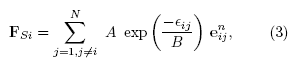
where N is the total number of pedestrians in the system, A and B are constants that determine the strength and range of the social interaction, e- is the unit vector pointing from particle pj to pf, this direction is the normal direction between two partióles, and eij is defined as
![]()
where d^ is the distance between the centers of pn andpj, and r is their corresponding particle radius.
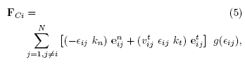
where the tangential unit vector (e* ) indicates the perpendicular direction of e-, kn and kt are the normal and tangential elastic restorative constants, v\a is the tangential projection of the relative velocity seen from Pj(Víj = vi - vi), and the function g(tij) is: g = 1 if eij < 0 (if partióles overlap) or g = 0 otherwise.
Because this versión of the SFM does not pro-vide any self-stopping mechanism for the partióles, it cannot reproduce the fundamental diagram of pedestrian trafile as shown in Ref. [18]. Conse-quently, the modification consists on providing virtual pedestrians with a way to stop pushing other pedestrians. This is achieved by incorporating a circular respect área cióse to and ahead of the particle (pi). The center of this circular área is located at the résped distance (Dm) from the center of the particle p¿, also having Dm as its radius, and in the direction of the desired velocity. The respect distance is parametrized for each particle depending on its own radius, D¡n = Rp x r¿, Rp being the respect factor. While any other pedestrian is inside this respect área, the desired velocity of pedestrians (pi) is set equal to zero (vdi= 0). For further de-tails and benefits of this modification to the SFM, we refer the reader to Ref. [18].
ii. Contractile particle model
This model was proposed by Baglietto and Parisi [20] and it is useful for modeling pedestrian flows in normal conditions. It consists of a set of rules defining autómata partióles that can move on the real plañe. It has the benefit of being computa-tionally faster than force-based models and it can reproduce very well specific flow rates and fundamental diagrams of different experiments reported in the bibliography by only changing the parame-ters related to the particle radii.
The model consists of partióles of variable radii. Each radius can range between rm¿ and rmax in a continuous way. The minimum radii are associ-ated with the máximum physical compressibility of the pedestrian and the máximum radii are related to the necessary personal space needed for taking normal steps under low density conditions. The particle has a desired velocity (v,¡¿) pointing at the desired target location and its magnitude (vdi) is a function of the particle radius (r¿). When a particle (pi) enters in contact with a boundary, obstacle or another particle, an escape velocity (ve¿) appears, having a fixed magnitude (ve) and opposite direction to the interaction. Then, the particle radius instantaneously collapses to rm¿.
The relation between the radius and the desired speed must fulfill vd(rmin) = 0 and vd(rmax) = Vdmax with a functional form given by Eq. (6):

where vimax is the desired speed at which a pedestrian would walk in an open and free space and 3 is a constant.
When a particle is free of contact with any other particle or boundary, its radius increases in each time step according to
where the constant t is set to t = 0.5 s and At is the time step for computing the evolution of the system. Once r reaches rmax, it stops increasing.
Finally, in each iteration, the positions of partióles are updated by the equation
![]()
More details of this model can be found in Ref. [20]
III. Simulation Results
We present the results of simulations with two different models analyzing variations of the geometri-cal parameters Lb and dw (see Fig. 1) and looking at the total evacuation time and the specific flow patterns inside the room.
In the subsections i., ii. and iii., the exit width (6) is fixed at 6 = 1.2 m, the initial number of pedestrians is N = 200, which are uniformly distributed inside a squared room of 20 x 20 m ; this configuration generates an initial density p = 0.5 particles/m2.
The pedestrians behavior corresponds to normal conditions (competitive behavior with pushing and shoving are excluded in the present paper). The simulated pedestrians plan simply consists of mov-ing toward the nearest point of a segment placed centered and parallel to the exit line (with a size 0.2 m shorter than the exit width), and then toward a second target placed at a long distance location beyond the end of the bottleneck.
In Fig. 2, the geometry and typical configura-tions of simulated pedestrians are shown for the two models used.
i. Bottleneck length
First, we consider simulations with the social forcé model with a respect área. The parameters used are uniformly distributed in the following ranges: pedestrian mass m [70 kg, 90 kg]; shoulder width 2 x r G [48 cm, 56 cm]; desired velocity Vd G [1.15 m/s, 1.45 m/s]. The constant parameters are: t = 0.5 s, A = 2000 N, B = 0.08 m, kn = 1.2 105 N/m, kt = 2.4 105 kg/m/s, and Rp = 0.7.
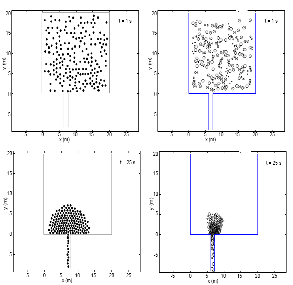
Figure 2: Snapshots of simulations. The left column displays two configurations of the system at different times for the simulations performed with the social force model with respect area. For the same times, the corresponding configurations of the system simulated with the contractile particle model are shown on the right column.

It is worth noting that because we are simulating normal conditions, the low valúes of tlie desired velocity (and the respect mechanism) lead to the absence of contact interaction [Eq. (5)] as can be seen in Fig. 2, bottom-left panel. This may suggest that under the present conditions the contact term of the SFM-respect has no influence on the results.
The total evacuation times as a function of bottleneck length are displayed in Fig. 3 for three dif-ferent valúes of dw. Each condition (each point in the figure) was simulated ten times with ini-tial positions uniformly distributed inside the room (p = 0.5 particles/m2).
As expected, the evacuation time increases with increasing valúes of Lb, confirming that imposing long boundaries after the exit has a negative influence on the evacuation performance. This influence grows rapidly over the first 1 or 2 meters and reaches an asymptotic valué of about 20% higher evacuation time with respect to the one of a clean exit. Both facts are in agreement with experimental studies [11,12] with a similar number of pedestrians (N = 180) and the same exit width (6 = 1.2 m). In particular for this model, the results for different
dw reveal that the proximity of the exit to the wall is favorable.
Now, we consider the simulation results of the contractile particle model (CPM). The model parameters used are: rmin = 0.10 m; f'max = 0.37 m; Ai = 0.05 s; vimax = 0.95 m/s; and ¡3 = 0.9. Figure 4 shows the total evacuation time as a function of the bottleneck length. The same tendency as in the previous model can be observed. It presents two main facts: (a) increasing evacuation time for increasing Lb , and (b) the asymptotic upper bound is reached at similar valúes of Lb- Furthermore, for the reference sce-nario of the exit far from the lateral wall, a similar percentage increase of the evacuation times is observed. However, the contractile particle model shows a reversed trend when the exit is near the lateral wall, increasing the evacuation time. This issue will be further discussed in next sections.
ii. Distance of the exit from the lateral wall
In this section, we present the results of mean evacuation times as a function of the distance of the exit from the nearest wall (dw). Figure 5 shows the re-lated information for three different valúes of Lb ■ In all cases, it can be observed that it is favorable to bring the exit near the sidewall. Also for thisgeometrical modification, the maximum reduction of the evacuation time is roughly 20%.
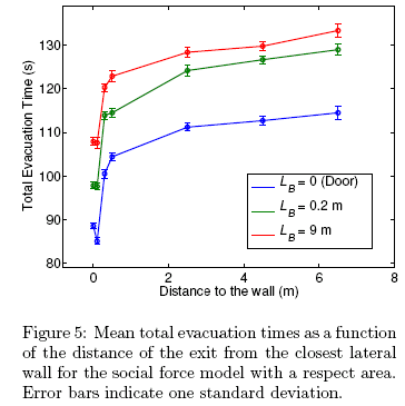
It must be noted that the maximum evacuation performance does not occur at dw = 0 m but at a slightly greater value, in the case of the door (LB = 0 m), at dw ∼ 0.1 m. This improvement in evacuation time for a location of the exit near the sidewalls is in accordance with mice experiments under competitive conditions [14].
On the contrary, the contractile particle model displays a slightly higher value of the evacuation time for the exit located near the wall, as indicated by the two curves in Fig. 4, which in the worst case (the door: dw = 0) is only 10%. The tendency to worsening the evacuation performance for lower dw is in accordance with another cellular automa-ton model [17]; however, in this case, the value is much higher, i.e., an increase of about 70% of the evacuation time.
It is worth emphasizing that, although both mod-els studied here (SFM-respect and CPM) were vali-dated by reproducing experimental flow rates at the exit for a geometry with a central door, when the geometry is changed the responses of the models are different. Thus, this standard way of validating pedestrian models may not be enough.
iii. Specific Flow Maps
In the present section, we will get some insight into the different evacuation times when different dis-tances of the exit from the lateral wall are consid-ered. To this end, specific flow maps will be com-puted and, again, we compare results using the two models described above.
Given a velocity field v(x,y) and a density field p{x,y), the specific flow field can be calculated as Js{x,y) = v{x,y) p{x,y) at any point (x,y) in-side the área of interest. This can be done at any time step, and then the average specific flow map Js{x,y) can be obtained.
This calculation was performed using the tool JPSreport, which is the analysis module of JuPed-Sim developed at the Forschungszentrum Jülich in Germany [21,22]. This tool implements an estab-lished protocol for calculating the density using Voronoi cells as described in Ref. [23].
We considered data with a frequency of one frame per second. Averages were computed between 30% and 70% of the total evacuation time for each run. Furthermore, the spatial grid (xm,yn), over which the different fields were computed, was a square grid of side 0.2 m.
In Fig. 6, the specific flow maps for both models are presented for the case of doors (Lg = 0).
The specific flow patterns reveal important dif-ferences between the examined models.
The upper panels, corresponding to the social forcé model with a respect área, show that the specific flow is greater along the walls. Thus, a wall orientated in the normal direction of the door will increase the output flow and henee, the evacuation time will be shorter.
On the other hand, the three lower panels show that the walls do not lead to any improvement in the flow. Instead, the higher valúes of Js oceur away from the walls, at the middle of the cluster of simulated pedestrians. So, having a wall perpendicular to and near the exit reduces the effective flow and increases the evacuation time.
iv. Size of the System
In order to check whether the improvement of the flow rate for shorter bottleneck length holds for larger systems, we also study the egress of N = 400 pedestrian from a room of 28.3 x 28.3 m and with the same door width (6 = 1.2 m) cen-tered at x = 14 m. The new dimensión of the room allows us to keep the same initial density (/3 = 0.5 particles/m2) as in the smaller system studied above. We simúlate this larger system by means of the contractile particle model.

Because we want to compare systems with dif-íerent N, it is more suitable to look at the specific flow that is shown in Fig. 7.
Both curves ofspecific flow (Js) as a function ofLg look similar, showing a decrease of Js as Lb increases, thus confirming the original result presented in section i. For the model used (CPM), the specific flow is a little bit higher in the case of N = 400 partióles, and the enhancement due to a shorter bottleneck length is more pronounced. In
the system of N = 200 particles, the percentage difference is about 18% when comparing the maxi-mum and minimum specific flows, but for the larger system (N = 400) this difference is 28%.
These results suggest that the door (or very short bottleneck) is the best option for any size of the system. We think this can be explained as it was already outlined in the introduction: a bottleneck reduces the available space after the exit, which produces a higher density that can decrease the flow (exceeding the capacity).
IV. Conclusions
In this paper, we studied the influence of two geometrical factors on the evacuation time: the botin the present study were validated considering the flow rate and the fundamental diagram in simple geometries. The global flow rate values measured in a configuration with a centered door are comparable with experimental ones. However, the mod-els respond in different ways under the geometrical change investigated, presenting very different spe-cific flow rate patterns inside the room. This can be a warning for the pedestrian dynamics community, and several geometries should be used for validat-ing output flow rates, instead of just using a single door far away from lateral walls. This is another reason for expecting new experimental data considering different geometries.
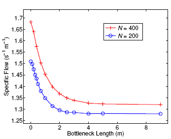
Figure 7: Specific flow as a function of bottleneck length for two system sizes of N = 200 and N = 400. In both cases, the initial density is the same (p = 0.5 particles/m2). Results correspond to simulations with the contractile particle model.
For evacuation at normal desired velocities ( 1 -1.3 m/s), both models agree in that the longer the bottleneck length after the exit, the longer the evac-uation time and, in particular, a door (which is a special case of bottleneck of length LB → 0 m) is the best option. These results also agree with ex-periments in very similar conditions [11, 12]. Fur-thermore, the convenience of using short bottle-necks seems to be independent of the number of simulated particles.
Regarding the convenience of moving the exit closer to the lateral wall, the two models used in this work do not agree, and pedestrian experiments are not reported in the literature. Furthermore, other models [15–17] provide contradictory results and thus, the optimal door position is an open question. Considering the possibility that placing the door near a sidewall could improve the evacuation performance, it would be worth exploring this geo-metrical modification experimentally in the future.
It is important to remark that both models used
Acknowledgements - This work was financially supported by Grant PICT2011 - 1238 (ANPCyT, Argentina); ITBACyT2015-33 (ITBA, Argentina); and Fundación Bunge & Born (Argentina).
1. P J Di Nenno (Ed.), SFPE Handbook of fire protection engineering, Society of Fire Protection Engineers and National Fire Protection Association, Quincy, Massachusetts (2002). [ Links ]
2. J Fruin, Pedestrian planning and design. The Metropolitan Association of Urban Designers and Environmental Planners, New York (1971). [ Links ]
3. IMO Correspondence Group, Interim guidelines for evacuation analyses for new and existing passenger ships, Technical Report MSC/Circ.1033, International Maritime Organization (2002). [ Links ]
4. SGSA, The green guide guide to safety at sports grounds, HSMO, London (2008). Available at: http://www.safetyatsportsgrounds.org.uk/sites/default/files/publications/green-guide.pdf [ Links ]
5. Department of The Environment and The Welsh Office, The building regulations, Ap-proved Document B-Section B1, HMSO, Lon-don (1992). [ Links ]
6. S P Hoogendoorn, W Daamen, Pedestrian behavior at bottlenecks, Transport. Sci. 39, 147 (2005). [ Links ]
7. T Kretz, A Gru¨nebohm, M Schreckenberg, Experimental study of pedestrian flow through a bottleneck, J. Stat. Mech. P10014 (2006). [ Links ]
8. A Seyfried, O Passon, B Steffen, M Boltes, T Rupprecht, W Klingsch, New insights into pedestrian flow through bottlenecks, Transport. Sci. 43, 395 (2009). [ Links ]
9. W Liao, A Seyfried, J Zhang, M Boltes, X Zheng, Y Zhao, Experimental study on pedestrian flow through wide bottleneck, Transport. Res. Procedia 2, 26 (2014). [ Links ]
10. W Liao, A Tordeux, A Seyfried, M Chraibi, K Drzycimski, X Zheng, Y Zhao, Measuring the steady state of pedestrian flow in bottleneck experiments, Physica A 461, 248 (2016). [ Links ]
11. J Liddle, A Seyfried, W Klingsch, T Rup-precht, A Schadschneider, A Winkens, An experimental study of pedestrian congestions: Influence of bottleneck width and length, arXiv:0911.4350 (2009). [ Links ]
12. T Rupprecht, W Klingsch, A Seyfried, In-fluence of geometry parameters on pedestrian flow through bottleneck, In: Pedestrian and Evacuation Dynamics, Eds. R D Peacock, E D Kuligowski, J D Averill, Pag. 71, Springer US (2011). [ Links ]
13. R Nagai, M Fukamachi, T Nagatani, Evacu-ation of crawlers and walkers from corridor through an exit, Physica A 367, 449 (2006). [ Links ]
14. P Lin, J Ma, Personal communication (2016). [ Links ]
15. D Yanagisawa, K Nishinari, Mean-field theory for pedestrian outflow through an exit, Phys. Rev. E 76, 061117 (2007). [ Links ]
16. T Ezaki, D Yanagisawa, K Nishinari, Pedestrian flow through multiple bottlenecks, Phys. Rev. E 86, 026118 (2012). [ Links ]
17. J Wu, X Wang, J Chen, G Shu, Y Li, The position of a door can significantly impact on pedestrians evacuation time in an emergency, Appl. Math. Comput. 258, 29 (2015).
18. D R Parisi, B M Gilman, H Moldovan, A modification of the social force model can reproduce experimental data of pedestrian flows in normal conditions, Physica A 388, 3600 (2009).
19. D Helbing, I Farkas, T Vicsek, Simulating dy-namical features of escape panic, Nature 407, 487 (2000).
20. G Baglietto, D R Parisi, Continuous-space automaton model for pedestrian dynamics, Phys. Rev. E. 83, 056117 (2011).
21. http://www.fz-juelich.de/ias/jsc/EN/Research /ModellingSimulation/CivilSecurityTraffic/ PedestrianDynamics/Activities/JuPedSim/ jupedsimNode.html
22. https://github.com/JuPedSim/JuPedSim
23. B Steffen, A Seyfried, Methods for measuring pedestrian density, flow, speed and direction with minimal scatter, Physica A 389, 1902 (2010).

